Wired and Wireless M-BUS sensors#
How to manually import M-Bus sensors#
If you only wish to add a couple of sensors this is the preferred way.
Note
If the sensor you would like to add is connected to an external non-MIVO M-Bus master then make sure the converter has been added to infrastructure before continuing with this tutorial. How to add an external M-Bus converter
-
Start by pressing the magic wand in the top right side of the page.

-
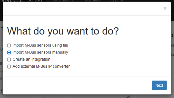
A dialog will appear, Select Import M-Bus sensors manually and press Next.
-
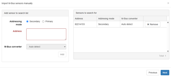
A new dialog box will appear where the new sensors address can be added on the left side.
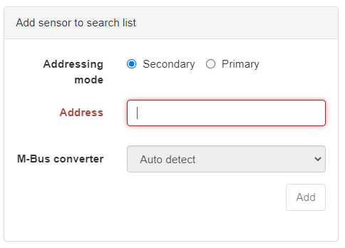
Using Secondary address
Enter the secondary address (often the same as the sensors serial number) and press Add or [Enter]. Repeat the step if you wish to add more than one sensor.
Using Primary address
Select Primary as addressing mode, enter the primary address and since the primary address is not unique you will also need to select on what M-Bus converter you wish to add the sensor.
-
On the right side there is now a list of all the sensors you wish to add
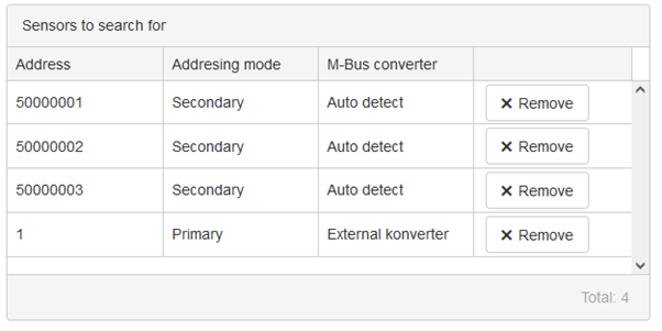
When all the sensors have been added proceed with the Next button.
-
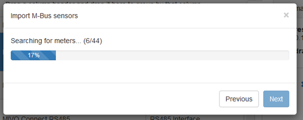
The device is now searching for the sensors
-
If there where any problem during the search the following step would be shown.
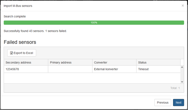
These sensors will not be imported, remember the failed sensors or export the list to excel by pressing 'export to excel'. When the issue has been located retry the procedure. Press Next to continue.
-
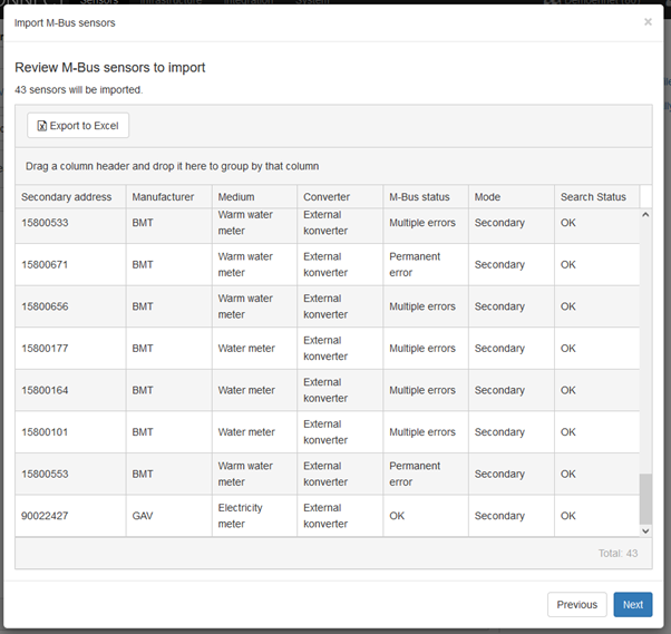
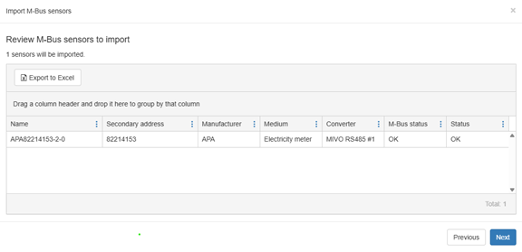
The next step is a detailed list of all the sensors that will be added to the system.
-
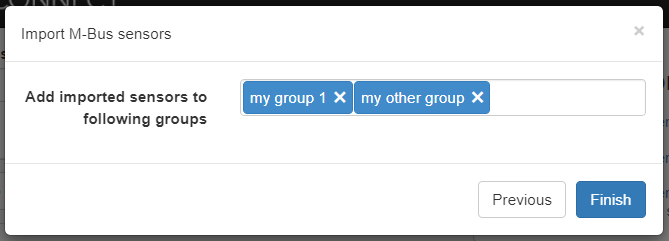
This is the last step of the wizard, here you have the option to specify new or existing groups to which the sensors should be added. To create a new group, enter its name and press the [Enter] key on your keyboard. When done press Finish.
-
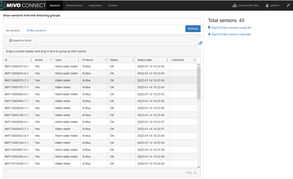
You are now done and the sensors should be visible in the Sensors view.
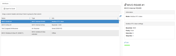
IEC1107 Sensors#
Import IEC1107 Meters via M-Bus in MIVO Connect
If you want to read an electricity meter that communicates via IEC1107, you can easily configure this directly in the MIVO Connect web interface – without the need for any external physical converter. By accessing the correct RS485 port and changing the type to IEC1107 → M-Bus converter, a virtual converter is created which internally translates IEC1107 communication into M-Bus within the system.
Step 1: Change RS485 Port to the Correct Type
- Go to Infrastructure in the MIVO Connect web interface.
- Identify the correct RS485 port (where the wire is directly connected to the device via A/B terminals).
- Click Edit on the corresponding port.
- Change the port type to
IEC1107 → M-Bus converter.
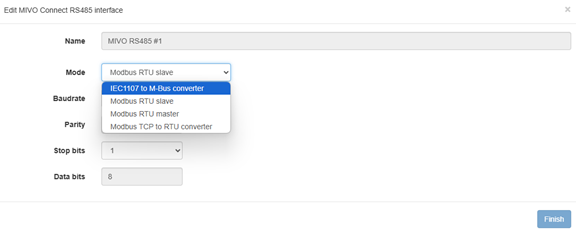
Once the RS485 port has been set to IEC1107 → M-Bus converter, the virtual converter is now active and ready to use. This means you can now start adding meters to MIVO Connect – but unlike standard M-Bus meters, they cannot be discovered automatically. Instead, you must add each meter manually.
Step 2: Add Meters Manually
- Click the magic wand in the top-right corner.
- Choose:
Add sensor > Add M-Bus sensors manually (wired and wireless) - Enter the secondary address or serial number of the meter.
- Click Add to include the meter in the list.
Step 3: Review and Import Meters
Once all meters have been added to the list, click Next to proceed.
You will now see an overview where each meter is displayed with its address and identifier.
After this, the process is complete. You can choose to:
- Import the meters into an existing group, or
- Create a new group to manage meter data from the selected meters.
Modbus sensors#
Guide: Add Modbus Sensors Manually in MIVO Connect#
This guide walks you step-by-step through how to manually create a Modbus sensor template in MIVO Connect and ensure correct communication using the meter’s datasheet.
Step 1 – Choose "Add Modbus sensors manually"#
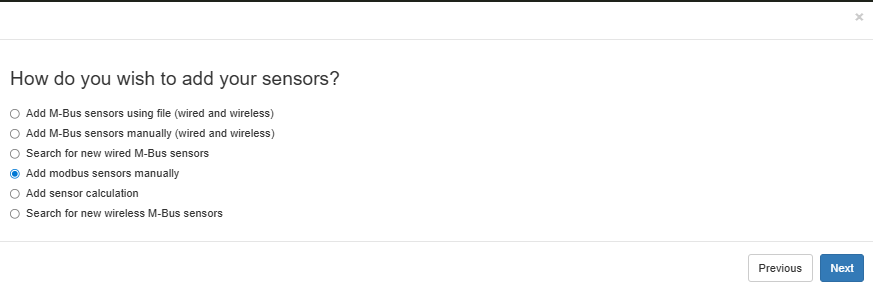
Click the magic wand in the top right corner and select:
Add sensorsAdd modbus sensors manually
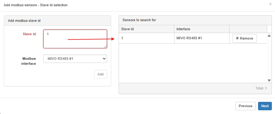
Step 2 – Enter Slave ID and Interface#
This step defines which Modbus device (slave) MIVO should communicate with.
- Slave ID: The unique Modbus address for your device. This must exactly match what is configured in the meter.
- Modbus interface: Select the correct RS485 port (or TCP interface if using Modbus TCP).
Important: If multiple devices are on the same Modbus bus (RS485), each must have a unique Slave ID. If not, communication conflicts will occur.
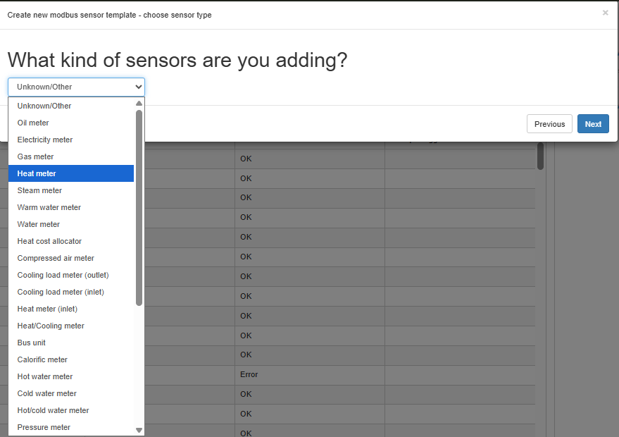
Step 3 – Select Sensor Type#
Choose what type of meter you’re creating the template for. This affects how data is presented in the UI.
Examples:
- Heat meter
- Electricity meter
- Cooling load meter
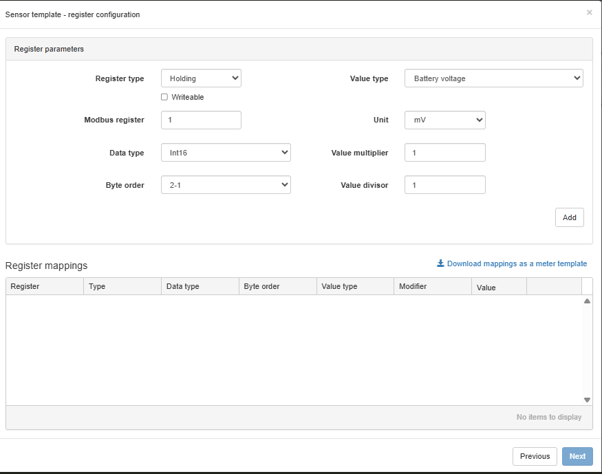
Step 4 – Add Register Mappings#
Here you define each measurement point to be read from the meter.
Fields to configure:
- Register type: Typically Holding.
- Modbus register: Start address from the meter's datasheet (note: may be 0- or 1-based indexing).
- Data type: Examples include INT16, FLOAT32, UINT32. Must exactly match how data is stored in the meter.
- Byte order: Critical! E.g., 2-1, 4-3-2-1. Also known as endianness.
- Value type: Select what the register represents (e.g., Heat energy, Flow, Voltage).
- Unit: e.g., kWh, m3/h, °C.
Tip: Always refer to the official datasheet from the manufacturer. It includes the correct register address, data type, and byte order.
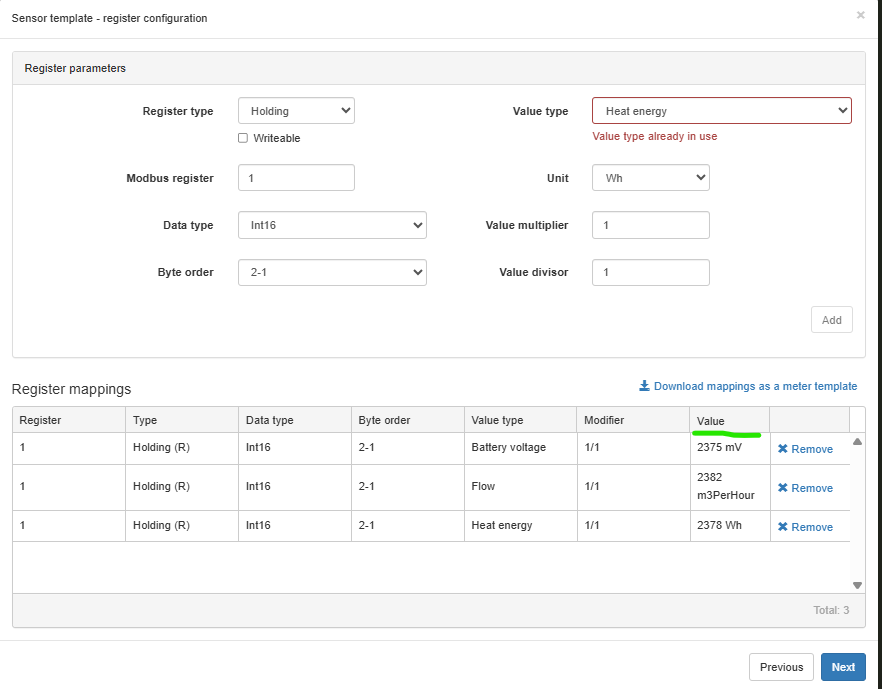
Step 5 – Confirm Register Mappings#
Once you click Add, the register is added to the mapping list. You will see:
- Register address
- Data type and byte order
- Value preview
- Value modifier and unit
Validation Tip: If you see a real value appear (not just 0), you know your settings are most likely correct. If values seem wrong or zero – it’s usually a sign of incorrect data type, byte order, or address.
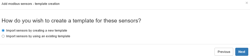
Bonus – Reuse the template for the next meter#
Once you've created the register mappings, you can download and reuse the template!
- Click Download mappings as a meter template
- For the next identical meter, choose
Import sensors by using an existing templateinstead
This saves time if you're working with multiple meters of the same model!
Finish and Save#
Click Next to complete the setup.
The template is now stored, and your sensors will appear in the MIVO Connect interface where you can:
- Create reports
- Export via Modbus
- Monitor and log data
Remember!#
- The meter’s datasheet is your best friend – always check for register address, data type and byte order.
- Test registers one by one – if the value looks correct, you’re on the right track.
- It's better to create small, clean templates per meter type than mixing too much into one.
- Reuse templates to save time when working with identical devices!
Good luck with the integration! If you need help interpreting registers or byte orders – just ask.